Building a flow editor
Bringing our network tab to life with zero dependencies
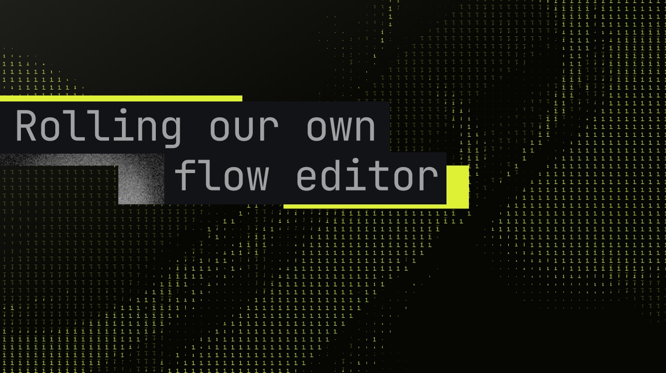
When we started building the network tab for our deployment platform, we wanted users to understand their API architecture at a glance: how traffic flows from the internet through gateways to instances, where bottlenecks occur, and which nodes are healthy or failing.
We wanted to ship this quickly with minimal effort, but existing libraries like React Flow aren't easy to configure. They offer fine-grained control over everything, but you still have to learn the ins and outs. Not just the person implementing it, but the entire team maintaining it needs to understand the framework. That's a deal breaker for us.
We also didn't need draggable nodes, re-attachable connection lines, or other fancy features. We just needed customizable nodes, clean connection lines, and proper hierarchical layouts.
So the decision was simple, we had to roll our own flow logic and components.
But, how?
What we needed was:
- Animated grid-like background
- Canvas-like structure for placing elements freely anywhere, for both nodes and overlay items (to show details for selected nodes)
- An engine that takes a tree-like structure and outputs non-overlapping positions for each node, then tells the UI which nodes to connect
- Simple way to style nodes without diving into the underlying code
Our main goal was to design an isolated piece of code that requires minimal maintenance and allows people to freely build on top of it.
We also had to decide between SVG and Canvas. Since we needed an easier way to control the DOM, we went with SVG, as we didn't have any performance-heavy requirements
Design of our infinite canvas
This is where we put all the canvas logic don't let the name deceive you, it's still SVG. It allows us to pan, zoom, and display our dotty background.
The API looks like this:
Since this accepts children, we can compose it however we want as long as it's proper SVG. The canvas also has constraints like maxZoom, minZoom, etc.
For every canvas operation, we use this state:
The scale helps us with zooming and offset with positioning thanks to this:
We pass this to the g SVG element. So technically, we don't zoom, we just make elements smaller and bigger.
Panning Logic
For moving we save the gap between mouse and origin at click, then maintain that exact gap by calculating newOrigin = currentMouse - savedGap on every mouse move.
Here's what happens under the hood:
This keeps the canvas glued to your cursor at the exact spot you grabbed it.
Zooming
For zooming we disable the native browser zoom. Otherwise, our canvas can't scale properly because the browser zooms before we actually scale stuff.
Grid Background
We render an animated dot grid using SVG patterns. Each dot pulses in size and opacity for visual interest.
Calculating the Layout
Now that we have a working canvas, we need to figure out where to place things. The layout system has two parts: a layout engine that calculates node positions and connection paths, and React components that render them.
The API looks like this:
The caller only needs to care about the data and how to style the things the layout engine produces.
Before we move forward, let's look at an example data:
The main challenge here is that we can have N number of gateways connected to internet and M number of instances connected to each gateway. We have to ensure there's no overlap and their directions are respected.
What the TreeLayout component does is:
- Accept the data from the API
- Call the layout engine and calculate positions and connection paths
- Finally, iterate over the
nodesandconnectionsthe engine produces
So our TreeLayout is basically just a shell, it calls the engine and glues everything together with React.
Flow of Layout Engine
The layout engine is where the magic happens. But before we can calculate anything, we need to know how big our nodes are. Since nodes are just components, we need their dimensions first. Right now we just hardcode the sizes since we know our node types ahead of time. Later, we could render them off-screen, measure them via DOM queries, and feed those dimensions to the engine. But that's overkill for now.
If you try to call calculate() before setting dimensions, the code panics. This is intentional, we want to catch errors during development. Otherwise, it's so easy to miss stuff, and later you start asking yourself, "what did I miss?"
Once we have dimensions, we call calculate() to figure out where everything goes. The core of this is buildNodeLayout(), which runs depth-first through the tree. The root node is easy: it's at level 0, position {x:0, y:0}.
Per-Node Direction Control
Here's a key design decision: each node controls how its children layout. The tree doesn't have one global direction, each node decides independently.
This is what lets the internet node spread gateways horizontally while each gateway spreads its instances horizontally. Without this, you'd need separate layout passes or complex conditional logic. Instead, the engine asks each node 'how do your children layout?' and recurses.
Configuration Tunability
The engine exposes several tuning parameters:
horizontalIndent/verticalOffset: Fine-tune child positioning relative to parentsubtreeOverlap: Controls how much subtrees can overlap (0-1 range). Lower values pack things tighter, higher values give more breathing roomverticalSiblingSpacing: Multiplier for vertical spacing between siblings in vertical layouts
We ship sensible defaults, but if you need precise control over layout density or alignment, people can easily configure it through props.
Fail-Fast
We use invariants throughout the engine. If dimensions are missing, if a node reference is invalid, if anything's wrong, the code panics immediately:
This is extremely useful technique to catch things during development. We follow this ideology everywhere in our codebase. Even our Go codebase follows that philosophy.
Depth-First Traversal
Once the engine has everything it needs, buildNodeLayout() walks the tree depth-first. We start at the root, process it, then recursively dive into the first child's entire subtree before moving to the next sibling. For this tree:
We end up with:
Traversing the tree and assigning levels is the easy part. The hard part is preventing overlap.
Preventing Overlap
Each level needs enough space for its widest subtree plus spacing. We calculate this bottom-up with calculateSubtreeWidth() (and calculateSubtreeHeight() for vertical layouts).
Here's an example:
inst-1,inst-2,inst-3,inst-4: width = 282 (base case, leaf nodes)gw-1subtree: width = 282 + 25 + 282 = 589 (two instances + spacing)gw-2subtree: width = 282 + 25 + 282 = 589 (two instances + spacing)INTERNETsubtree: width = 589 + 25 + 589 = 1203 (both gateways + spacing)
Horizontal Stacking
Now that we know the subtree widths, we can calculate actual X positions. The goal is to center all children under their parent.
If there's only one child, it centers directly under the parent. Simple.
For multiple children, we need to distribute them evenly. Let's say the parent is at X=0 and we have two instances that need a total width of 589.
When a node has direction="horizontal", its children spread horizontally at the same Y level, creating this left-to-right arrangement.
Vertical Positioning
For nodes stacked vertically (when the parent has direction="vertical"), we use:
Let's visualize this with INTERNET → gateways:
Calculation: 0 + 10 + 75 + 50 = 135
All siblings at the same level share the same Y coordinate since they spread horizontally. So gw-2 also sits at y=135, just at a different X position.
We could optimize this by calculating Y once per level instead of per-node, but for typical tree sizes the performance gain isn't worth the added complexity.
For vertical stacking within a group
Calculation:
Connection Lines
Straight lines between nodes would overlap and look messy. Instead, we route connections through intermediate waypoints, think of them as turning points that guide the line around obstacles.
Connection lines attach to node edges, not centers. We calculate each node's left, right, top, and bottom edges from its center position and dimensions. This gives us exact attachment points for clean connections.
For horizontal layouts (children spreading side-by-side), we use a Z-shaped path:
We calculate the midpoint of the vertical gap between parent's bottom and child's top. This creates symmetrical turns that look clean:
This is a 4-point path:
For vertical layouts (children stacking top-to-bottom), we use a trunk-and-branch pattern:
This creates a 3-point path:
All siblings share the same trunkX, creating that unified tree look.
And that's it. The engine spits out positioned nodes and connection paths.
Rendering the Connections
Once we have the waypoint paths, we need to actually draw them. First, let us show you how the raw waypoints look and you'll understand why we built something better.
See the red dots? Each one is a waypoint calculated by the layout engine.
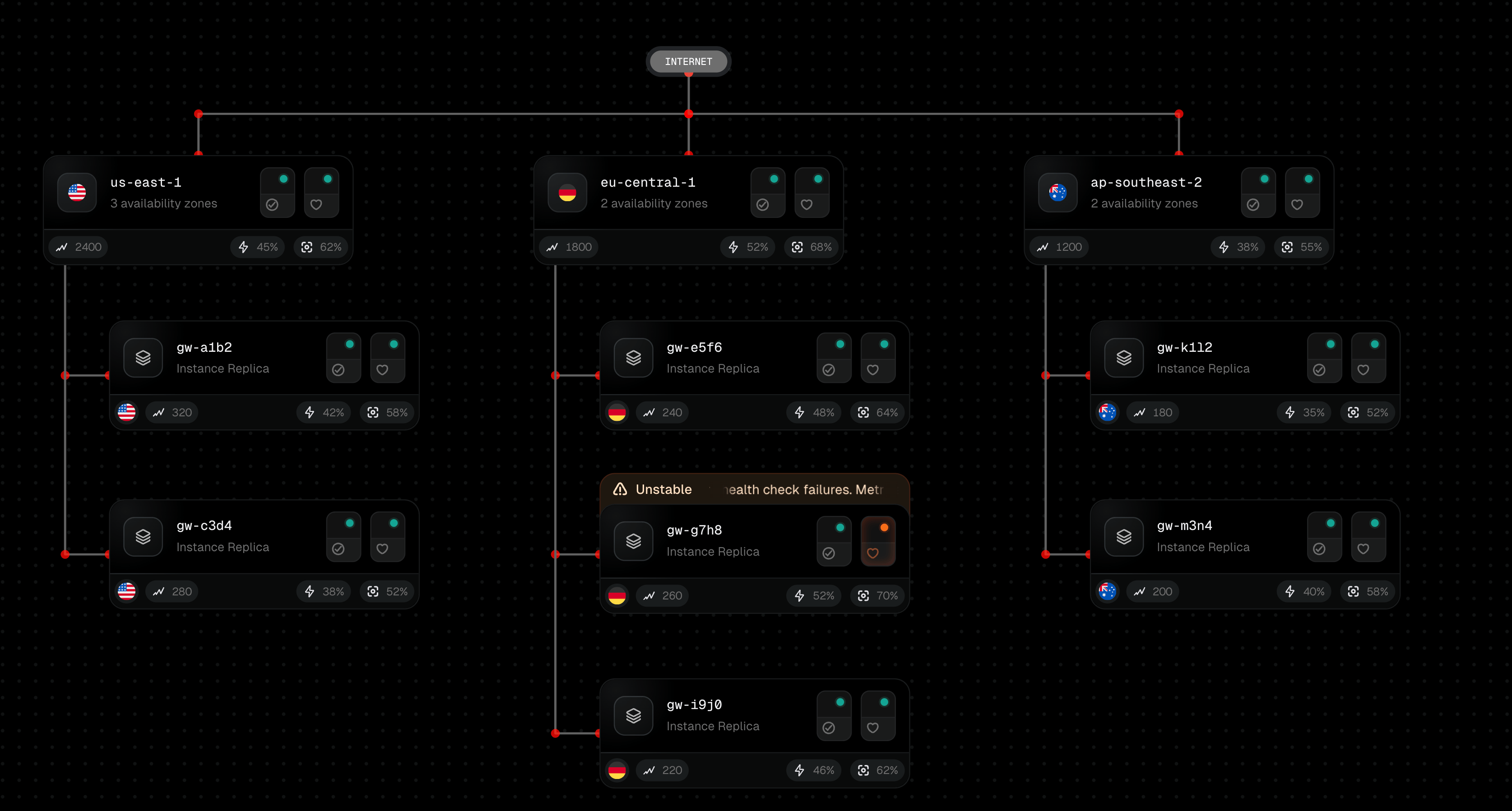
The solution is simple (it's not SVG math sucks), detect corners where the path changes direction (horizontal-to-vertical or vice versa), then replace those sharp angles with curves. We calculate entry and exit points around each corner and use the corner itself as the curve's control point. This creates natural-looking turns.
For animation, we use SVG's stroke-dasharray and animate stroke-dashoffset. This creates the moving dots/dashes effect without any JS animation:
What We Shipped
It handles our network tab perfectly: gateways spreading horizontally from the internet, instances spreading horizontally from gateways, smooth animated connections showing traffic flow. The entire team understands how it works. When we need to change something, we just change it.
Trade-offs We Made
We hardcode node dimensions because we know our node types ahead of time. A general-purpose library would need to render nodes off-screen, measure them, then feed those dimensions to the engine. Too much complexity for our use case.
The routing logic is baked in for our specific tree structure. If someone wanted to use this for an org chart or file system tree, they'd need to modify the engine. This is designed specifically for our deploy network.
Should You Roll Your Own?
Probably not. React Flow is excellent if you need the full feature set and don't mind the learning curve.
But if you know exactly what you need, go ahead. We shipped this fairly quick with zero dependencies, and the entire team understands how it works.